
Did you like the tool?
Did we solve your problem?
Rate the tool
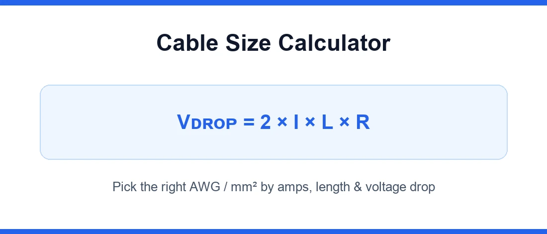
Hand a Cable Size Calculator the same inputs on a Monday and a Friday and it returns the same recommended size — but the conductor I actually pull is often a different one. Twenty-odd years of sizing conductors, from cramped control panels to boat switchboards, taught me to read that first result as a floor, not a finish line. The reason hides in a number most people never verify: how much voltage is lost by the time current reaches the far end of the run.
✓ Quick answer: a good tool gives you the minimum safe conductor size in seconds, but you finish the job with judgment. Check two things — can the conductor carry the load without overheating, and does it hold voltage at the load — then round up and, where it counts, get a qualified electrician to sign off.
Voltage Drop, Not Ampacity, Usually Settles the Size
Two checks decide every conductor. Whether it carries the load current continuously without overheating — that is ampacity, or current-carrying capacity. And whether it holds far-end voltage close enough to the source — that is voltage drop, the voltage lost along the run length. This is a two-part selection, and it is where beginners stall: they pass the first test, skip the second, and cannot work out why a compliant circuit still starves its equipment.
On short jumps, ampacity is king. Stretch the run out and voltage drop becomes the binding constraint — the number that forces a larger size long before continuous current ever would. Conductor resistance climbs with length; the acceptable voltage the load needs does not bend to meet it. So the honest read of any result is simple: ampacity sets the minimum safe conductor size, and voltage drop decides what you install. If drop is the only thing you are chasing, our dedicated voltage drop calculator isolates that one variable.
Skip the Garden-Hose Analogy — Here's What the Tool Settles
You will find wire sizing explained with a garden-hose analogy in half the pages online. It is harmless, but it buries the mechanics. What a cable sizing tool does is narrower and more useful: it runs a lookup against standardized tables and a voltage-drop method, then returns a recommended size. Underneath, it is balancing current-carrying capacity against voltage regulation while adjusting for the real-world factors that never make it into a tidy textbook diagram — heat, how the cable is installed, how many run together. Cable size selection is not one calculation; it is a selection from competing limits, and the tool's job is to surface the smallest conductor that clears all of them.
Two Worked Examples Beat Ten Paragraphs of Theory
A 120 V Branch Circuit (AWG)
Take a 120 V single-phase branch circuit pulling 20 A over a 30 ft one-way run length in copper, held to 3% max. The calculator lands on 12 AWG, and when you verify actual drop it comes in around a 1.9% voltage drop — comfortably inside the ceiling. Ampacity alone would have let you go smaller; the drop check is what pins it at 12 AWG.
The sizing sequence in miniature
Max allowable drop → max resistance the run allows → required area → round up to nearest standard size → verify actual drop.
A 12 V DC Solar Run (Metric)
Now a low voltage DC example — the kind that punishes sloppy work. A 12 V DC circuit carrying 15 A across a 100 ft run in copper, capped at 3%, gives you just 0.36 V of headroom. Plug it in and the required area works out near 42.7 mm², which is essentially AWG 1; I would round up to 1/0 for margin and peace of mind. Notice reactance drops out here — on DC, reactance X = 0, so the arithmetic is pure resistance. This is exactly why solar arrays, battery bank wiring, inverters, charge controllers, and 12 V actuators swallow bigger conductors than their modest amperage suggests.
The Math the Calculator Is Running, for the Curious
If you want to check the tool's homework, the core relationships are short.
The multiplier reflects the round-trip conductor path — a ×2 factor for single-phase (current runs out and back through the hot conductor and neutral conductor) and a √3 factor for three-phase — so K = 2 or K = √3 depending on phase. In the area formula, D is the one-way distance and ρ is resistivity, which you flip to read the current a given cross-section supports within the limit.
Resistivity is not a constant, which trips people up. It is temperature-dependent: ρ = ρ₁[1 + α(T − T₁)], where α is the temperature coefficient. Copper resistivity and aluminium resistivity both climb as conductors heat, so a cable that passed at 20 °C can drift once it is at operating temperature. The old US circular mils approach bakes the identical physics into different units.
Copper, Aluminium, and the "Bigger Is Always Safer" Myth
Material choice — the conductor material — is the first fork, and here is a contrarian take that earns me side-eye on job sites: oversizing is not free safety. Copper earns its price with higher conductivity, better corrosion resistance, and easier termination; for the same ampacity it is a smaller conductor size, simpler to route and terminate. Aluminium carries roughly 64% higher resistance for an equal size, so it needs a larger size to hit equal voltage drop and shows lower ampacity per gauge. But it is cheaper, and on large runs — service feeders, long hauls — that conductor cost gap is real money, provided you use proper terminations rated for it.
Where "bigger is safer" collapses: an oversized cable is expensive, adds install difficulty, and a conductor too fat for its lugs invites bad joints — which is its own fire risk. The target is not maximum copper. It is the sweet spot where the conductor is thin enough to terminate cleanly and sit in its raceway, yet thick enough to hold voltage. A thinner conductor that meets every limit beats a bloated one fighting its terminations.
Derating: Where Clean Numbers Quietly Fall Apart
The calculator's tidy result assumes ideal ambient conditions. Reality applies correction factors, and this is where I have watched more installs fail than in the raw sizing math. When you toggle Engineer Mode in our Cable Size Calculator, you unlock those variables. Ambient temperature is the big one — a conductor rated in a cool lab loses ampacity in a hot attic or boiler room, so the tool applies thermal derating multipliers, a derating factor that increases the required wire size, rather than letting you upsize by guesswork. Bundling matters just as much: grouping several current-carrying conductors together, or stuffing a conduit past sensible conduit fill, traps heat because the bundles cannot shed it. Trapped heat means less heat dissipation; left unchecked that is heat buildup and, eventually, overheating. If you are designing a whole panel, lean on our other engineering calculators to keep the rest of the system in step.
Installation methods rewrite the numbers too. The same cable carries different currents in air, clipped to a surface, spaced from a surface, run in conduit, or buried. Metric standards even fix a standard depth of burial — typically 0.5 m — and apply a depth rating factor when you deviate. Then there are non-linear loads: switch-mode supplies and drives inject harmonics that heat conductors past what the plain current suggests. Every one of these is a real-world factor the current-carrying table cannot see until you tell it, and each drags you below what the ampacity tables promise. Good tools fold the lot into a derating wizard so you are not hand-stacking a correction factor for every condition.
💡 Tip: In Engineer Mode, enter the ambient temperature and the number of bundled circuits sharing the conduit before you read the size. Those two grouping factors move the design current — and often bump the recommended conductor a full size — so setting them first keeps the result honest.
One Calculator, Four Rulebooks
A recurring surprise: "cable size calculator" does not name one method — it means whichever governing code you are under. In the US, the NEC drives ampacity and voltage-drop practice. According to the standards published by the National Fire Protection Association (NFPA) within the National Electrical Code, the NEC recommendation is roughly 3% branch circuits, 5% feeders, and ≤5% combined, tightening to 2–3% critical loads for sensitive loads and precision loads. Cross the Atlantic and it is the BS7671 18th Edition — the IEE Wiring Regulations — across the UK, or the international IEC 60364-5-52 that underpins international wiring systems and most GCC practice. Down under, AS/NZS 3008.1.1 handles the cable-sizing calculations and AS/NZS 3000 the wiring rules, covering circuits up to 1000 V AC or 1500 V DC. Boats keep their own book: ABYC E-11 for marine AC/DC systems. Metric rules generally cap drop near 5% nominal voltage, and many designers pull tighter, to 2.5%, on long feeders.
Two things hold across all of them: the physics ignores your flag, and code compliance is a floor, not a target. Whatever the recommended size, a qualified person signs off on the install.
Cable Types the Metric World Will Throw at You
US installers think in AWG and KCMIL; step into IEC/BS territory and you are suddenly choosing a cable type by construction. Armoured cable — SWA or AWA — for buried and mechanically exposed runs. Twin & earth (the 6242Y you see in domestic work) and 6491X singles for conduit. When smoke and fumes matter, LSZH constructions like H07Z-K replace PVC, and flexible feeds might use flexible cords such as SY cable. You will pick single-core or multicore, and you will match the insulation temperature rating to the terminal: 70 °C thermoplastic versus 90 °C thermosetting changes the current the same copper can carry, because a higher temperature limit means a higher current-carrying table entry. Ampacity tables are indexed to that insulation temperature — get the temperature rating wrong and every downstream number is off.
The Conductors Everyone Forgets: Earth and Neutral
Sizing the live conductor is only half the job. The earth conductor — the CPC or protective conductor in BS/IEC language, the EGC or grounding conductor under NEC 250 in the US — has to be sized too. Pull it from a lookup table, or better, size it by calculation so it satisfies the earth-fault loop impedance the protective device needs to trip in time. Neutral sizing hides its own trap: on an unbalanced three-phase system, or one feeding non-linear loads, the neutral can carry as much as a phase and cannot default to a token size. For very large loads, do not chase one monster conductor — parallel conductors, run as balanced cable groups, handle high-current runs far more sanely. And where fault energy is high, a short-circuit rating (the fault-current rating) check becomes the third constraint alongside ampacity and drop.
Single-Phase vs Three-Phase, and Why Three-Phase Lets You Shrink the Copper
The supply type quietly sets your conductor size. On single-phase, current flows out and back down the full resistance path — that is the ×2 factor in the drop math, and on single-phase 230 V the penalty is baked in. Three-phase is more forgiving: the √3 factor reflects a shorter effective resistance path, so for equal power you draw less current, get lower voltage drop per unit power, and can run smaller conductors. On three-phase 400 V, that efficient transmission is why the same kW lands on a slimmer cable than 120 V or 240 V single-phase would allow. Power factor plays in too — metric tools often assume PF 0.8, while AS/NZS expects PF 0.9 lagging — because a poorer power factor drags more current for the same real load, and motor starting only sharpens it.
Motors, Inrush, and Sizing for the Load You'll Have in Five Years
Two forward-looking habits separate clean installs from callbacks. First, motors. A motor's inrush current — the motor starting current, commonly 6–8× running current (also written 6–8× full-load current) — will not change the ampacity-based conductor, but it can cause voltage dips that trip controls or stall the start. On critical branch circuit motor wire sizing, I check the drop at that starting current, not just running current, so the voltage dip stays survivable. Second, future load growth: the copper you install today should carry headroom for the load you add tomorrow. A small upsize now — sometimes just one gauge thicker for a sensible safety margin — is far cheaper than recabling a full run later. Oversizing for its own sake is waste; oversizing against a known growth curve is engineering.
How to Actually Drive the Calculator
I buried the instructions on purpose — the thinking above matters more than the button-pushing. But here is the flow. Feed it the load current in amps (A), or the power in watts (W) or kW and let it derive the current. Give it the one-way run length in ft or m, the system voltage (120 V, 240 V, 230 V, 400 V, or a 12/24/48 V DC bank), the phase, and the conductor material — copper or aluminium. Set the insulation temperature rating, the installation method, the ambient temperature, and any grouping or conduit detail. Pick your allowable voltage drop % — the max allowable voltage drop % you will accept, commonly 3%. Hit Calculate.
What comes back: a recommended size, the actual voltage drop it will see, the cross-sectional area, and the ampacity headroom — often across several cable types at once. Ours adds a plain-English explanation, an interactive visualizer with live sliders, a short video walkthrough, and an AWG to mm² converter so US and metric users read the same answer. Toggle units and the conversion table redraws — cross-sectional area in mm² and circular mils, conductor diameter in inches and mm, KCMIL for the big stuff — alongside a downloadable cable size reference chart and reference table. Punch in a quick example — say 8 A over a 50 ft one-way run at 120 V, copper, 3% — and read the size it returns. That is cable size selection, step by step.
A Quick-Reference Starting Point (Then Verify With the Tool)
These are ampacity floors at common temperature ratings for short runs. Voltage drop over any real cable run distance routinely pushes you one or two sizes up, so treat the table as a sanity check, then let the calculator do the cross-section math for your exact distance.
The Bottom Line
Undersizing shows up as excess voltage drop — voltage starvation, tripped breakers, nuisance trips, and eventually equipment damage or premature failure. An undersized cable overheating in a wall is a real fire hazard, not a theoretical one. Oversizing shows up as wasted money and, through poor joints, wasted energy. Between them sits the balance the tool exists to find: the smallest conductor that keeps stable voltage at the load with no equipment malfunction and no energy waste. Use the calculator to get the recommended size fast; use judgment — and a qualified electrician — to install it. Speccing a whole board? Once your conductors are sized, our resistor color code calculator handles the component side.
Disclaimer: This Cable Size Calculator is provided for general estimation and planning. Results depend on correct inputs and real installation conditions. For safety-critical or regulated work, verify independently against your governing code and have a qualified electrician confirm the final install.
Frequently Asked Questions
What size cable do I need for a given number of amps over a distance?
Start with ampacity — the conductor has to carry the amps and the load current continuously — then apply the voltage-drop method for your distance. Over a short cable run distance, ampacity usually wins, so a 20 A circuit sits near 12 AWG. On longer runs, voltage drop takes over and pushes you larger. As a quick example, 30 A on a short run wants 10 AWG, but stretch the same load out and 8 AWG or bigger becomes the honest answer. Enter your exact amps, distance, voltage, and material and let the tool size the conductor precisely instead of eyeballing a chart.
What's the difference between ampacity and voltage drop — and which one sets the size?
Ampacity is a thermal limit: the current a conductor carries before it exceeds its temperature limit. Voltage drop is an efficiency limit: how much voltage the run loses along the way. They are independent — a conductor size can pass one and fail the other. Ampacity (current-carrying capacity) sets a hard safety floor; on longer runs voltage drop becomes the binding constraint and dictates the final, larger size. Always size to whichever is more demanding for your particular run.
What voltage-drop percentage should I use?
Follow your code. The NEC recommendation in the US is about 3% on a 3% branch circuit and 5% on a 5% feeder, with the combined total kept at or under 5%; drop to 2–3% for sensitive or critical loads. Metric rules (IEC, BS, AS) generally allow up to 5%, and many engineers tighten to 2.5% on long feeders. A tighter voltage drop percentage means bigger conductors — it is a cost-versus-stability trade, and the calculator shows the size penalty of each target instantly.
Copper or aluminium — how much does the material change the size?
A lot. For the same ampacity, aluminium needs a larger size because it carries higher resistance than copper — its lower conductivity means roughly one to two sizes up to hold equal voltage drop. Copper stays a smaller conductor size and terminates more easily; aluminium wins on conductor cost for large runs. Neither is universally "better" — it is a cost, space, and termination trade. Set the conductor material in the calculator and it re-sizes automatically so you can compare both side by side.
When should I go one size up beyond the calculated result?
Whenever the future looks bigger than the present. Upsize for likely future load growth, for a high ambient temperature location, or for heavy bundling and conduit fill where derating bites. One gauge thicker is a cheap safety margin against long runs and added load, and far less painful than recabling. Do not oversize blindly, though — a conductor too fat for its lugs fights its terminations. Size for the real conditions plus a sensible margin, not for fear.
How do I choose the right cable size step by step?
Work the sequence: (1) find the load current from amps or power; (2) set the system voltage and phase; (3) pick the conductor material, cable type, and installation method; (4) choose your allowable drop; (5) let the tool return the ampacity-safe size, then verify the voltage drop over your run length; (6) apply derating for temperature and grouping; (7) round up to nearest standard size. That is cable size selection in practice — each input narrows the answer.
Why does voltage drop matter more on DC than AC?
Because the percentage is unforgiving at low voltage. A fixed absolute drop of, say, 0.5 V is trivial on 240 V AC but brutal on a 12 V, 24 V, or 48 V DC system — the same absolute voltage drop is a far bigger percentage voltage drop of the supply. That is why solar and battery wiring at 12/24/48 V demands oversized-looking conductors: there is simply less voltage to spare, so even small losses starve the load. On DC, reactance drops out, so it is pure resistance — but the low-voltage math is what bites.
How do I account for motor starting and inrush current?
Size the conductor for the motor's continuous running current first, then sanity-check the voltage dip during starting. Inrush current — the motor starting current, commonly 6–8× full-load current — is brief but can sag the supply enough to drop out contactors or stall the motor. For critical branch circuit motor wire sizing, confirm the drop at that starting current stays within limits, not just the steady-state figure. A soft starter or a slightly larger conductor tames the dip.
How do AWG and mm² convert?
There is no clean one-to-one, but the working equivalents are close enough to memorize: 14 AWG ≈ 2.5 mm², 12 AWG ≈ 4 mm², 10 AWG ≈ 6 mm², 8 AWG ≈ 10 mm², 6 AWG ≈ 16 mm². AWG counts a gauge number that shrinks as the wire grows; mm² measures cross-sectional area directly. Our conversion table and reference table sit beside the result so US and metric readers land on the same conductor — toggle and the numbers redraw in inches or mm.
Does the calculator follow NEC or IEC/BS?
Both — you pick the governing code and it applies the matching tables and drop limits. Choose NEC for US ampacity and voltage-drop practice, IEC 60364-5-52 or BS7671 for metric work, or AS/NZS for Australia and New Zealand. The physics is identical; only the tables, correction factors, and the accepted nominal voltage drop change. Set your standard first so the recommended size reflects the code you will be inspected against — code compliance starts with picking the right rulebook.